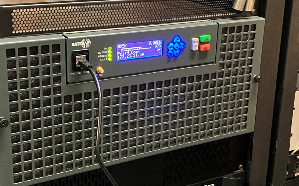
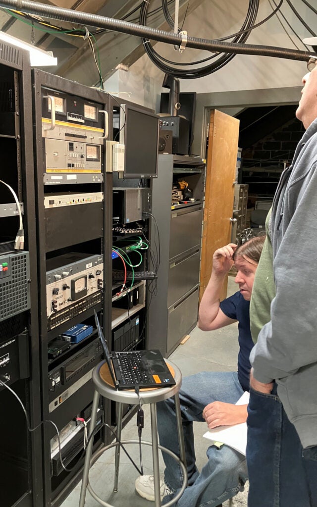
WMUL-FM’s new transmitter is installed and blanketing the tri-state with our music, news, sports, and other special programming.
So, what’s been going on over the past six months?
The Short / Less Technical Version
Back on June 10, 2024, WMUL-FM suffered a component failure in its transmitter and went off the air. WMUL-FM’s engineering staff spent more than a week diagnosing and trying to work around the problem. Partial service was restored on June 18th with a signal that would barely cover the City of Huntington.
The engineering staff determined that a new transmitter was required to restore full service. That new transmitter was fired up on December 12th.
What’s the Transmitter?
The transmitter is the device that takes an ordinary audio signal (very similar to the signal that comes out of a headphone jack) and turns it into a powerful radio signal. That radio signal is sent through a heavy cable called a transmission line up the tower to the antenna. WMUL-FM’s transmitter is located in a climate-controlled room on the fifth floor of the Science Building on Marshall University’s Huntington campus. The tower and antenna are located on the roof of the Science Building.
The next two photographs are of WMUL-FM’s tower and antenna atop the Science Building.
The Long / More Technical Version
This journey actually started a few weeks earlier, on Saturday, May 18, 2024. The day of Dr. Bailey’s wedding. As dinner was winding down, WMUL-FM’s engineering staff received alerts that the transmitter was off the air.
After rushing to the transmitter room (while still obeying the speed limit), we determined that this problem was an easy one to fix. A fan in the exciter had gone bad. The exciter is the first stage of the transmitter. It takes the audio signal and converts it to a radio signal, but only at 3 watts of power.
A temporary fan was rigged up and WMUL-FM returned to the air after less than 2 hours.
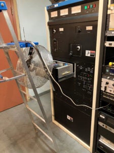
A new permanent fan was ordered and, on June 10th, WMUL-FM signed off for what should have been only an hour-long fan replacement. Unfortunately, that was the beginning of a six-month long ordeal.
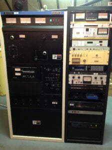
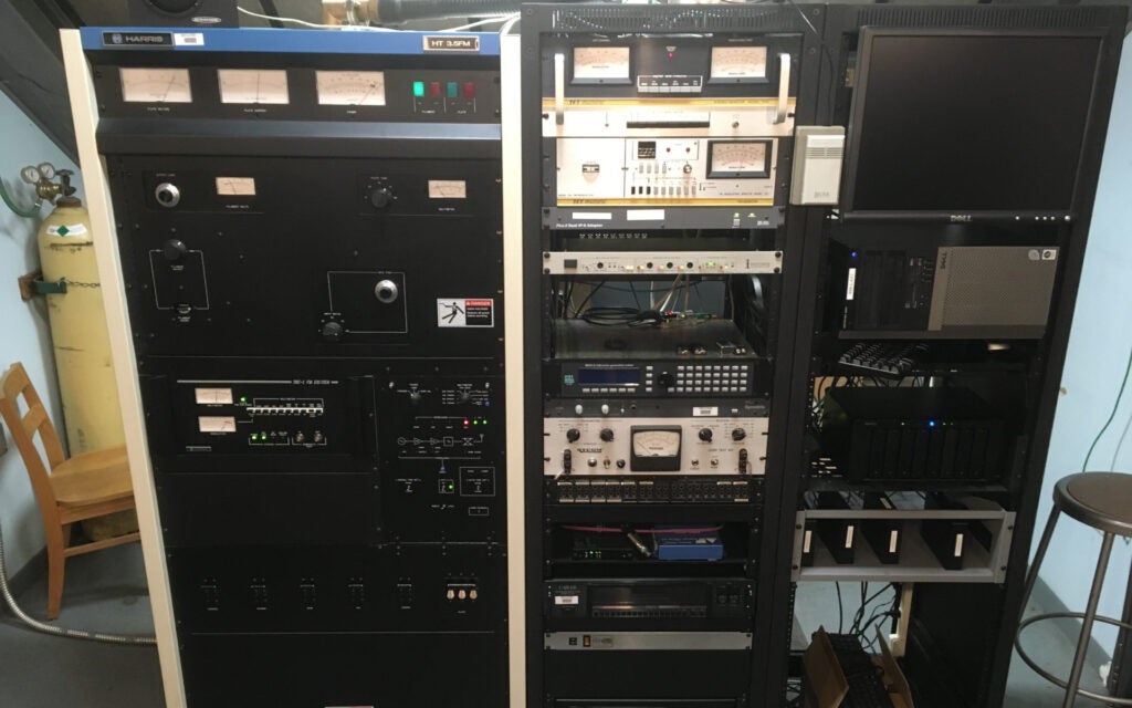
The transmitter is the larger cabinet on the left with the white / beige side panels. The Harris HT 3.K FM transmitter, purchased in 1989, was about the size of a refrigerator. The exciter installed in the middle of it was a Harris THE-1 and was purchased at the same time.
Replacing the fan itself was a quick and simple task. However, when we tried to turn the transmitter back on, something failed inside it.
We went to work trouble-shooting the components of the transmitter. The first failed item that we discovered was a 155-watt 5.5-ohm resistor. It was replaced with a spare and we tried again to turn the transmitter back on.
This video shows what happened to that replacement resistor.
So, the real problem was not the failed resistor. We did some more trouble-shooting and tried again with another resistor. That also did not work.
The problem seemed to be somewhere in the final power amplifier stage of the transmitter (the tube). This stage of the transmitter receives an 80-watt radio signal and amplifies it up to 3,300 watts to feed to the antenna.
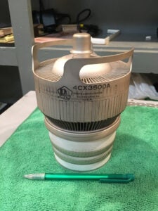
At that point, we determined that either additional replacement parts or a new transmitter would be required. So, we turned our attention to making a temporary repair just to get something back on the air.
Our first attempt was to use an old spare antenna that was already installed on the tower and an old 150-watt transmitter. Both the antenna and the transmitter had been used by WMUL-FM during the 1980’s. Unfortunately, both the antenna and the old transmitter were no longer usable.
Our second, successful, attempt was to install another old spare antenna above the roof of the Science Building. This is the same type of spare antenna that is up on the tower.
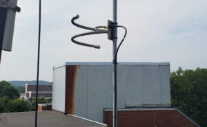
We connected this antenna to the Intermediate Power Amplifier (IPA) stage of the transmitter. This part of the transmitter was still fully functional. The IPA is the middle stage of the transmitter. It takes the 3-watt radio signal from the exciter and amplifies it up to 80 watts. That 80 watts is normally sent to final power amplifier (the tube).
Unfortunately, due to the devices using different connectors, there was not an easy way to connect the IPA to WMUL-FM’s main antenna. There is a procedure that could have accomplished this. However, it involved disassembling part of the transmitter in a way that, in our opinion, would not have been reversible with the 35-year-old transmitter. At that point, we were still hoping to repair rather than replace.
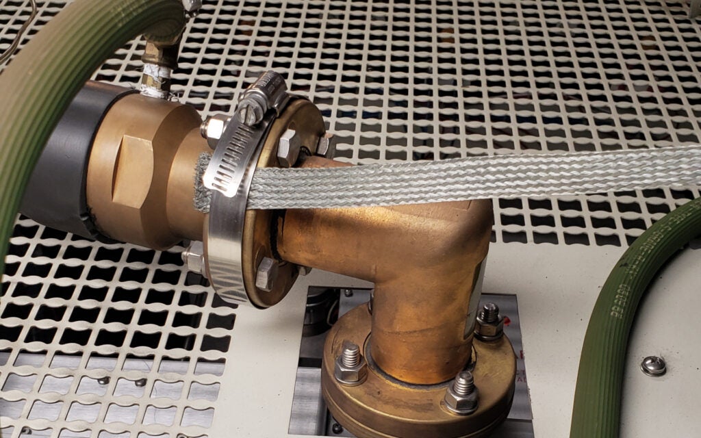
The transmitter and antenna are connected via a heavy cable called a transmission line. WMUL-FM’s main transmitter and antenna use a 1 5/8” EIA connector. The IPA and the spare antenna use a 5/8” N connector.
With these reduced facilities, WMUL-FM was able to return to the air the afternoon of Monday, June 18th. WMUL-FM applied for and received Special Temporary Authorization from the FCC to operate with these facilities until approximately the end of the year.
WMUL-FM’s coverage was significantly reduced. With our licensed facilities (1,400 watts Effective Radiated Power from an antenna 135 feet above ground level), WMUL-FM could be heard in most of Cabell County, W.Va. and Boyd County, Ky. as well as northern Wayne County W. Va. and southern Lawrence County, Ohio. With our emergency facilities (33 watts Effective Radiated Power from an antenna 66 feet above ground level), WMUL-FM could barely cover the City of Huntington.
We eventually determined that the only path forward was to replace the transmitter. WMUL-FM selected the GatesAir Flexiva GX5K. (Harris became GatesAir in 2014.)
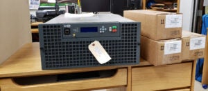
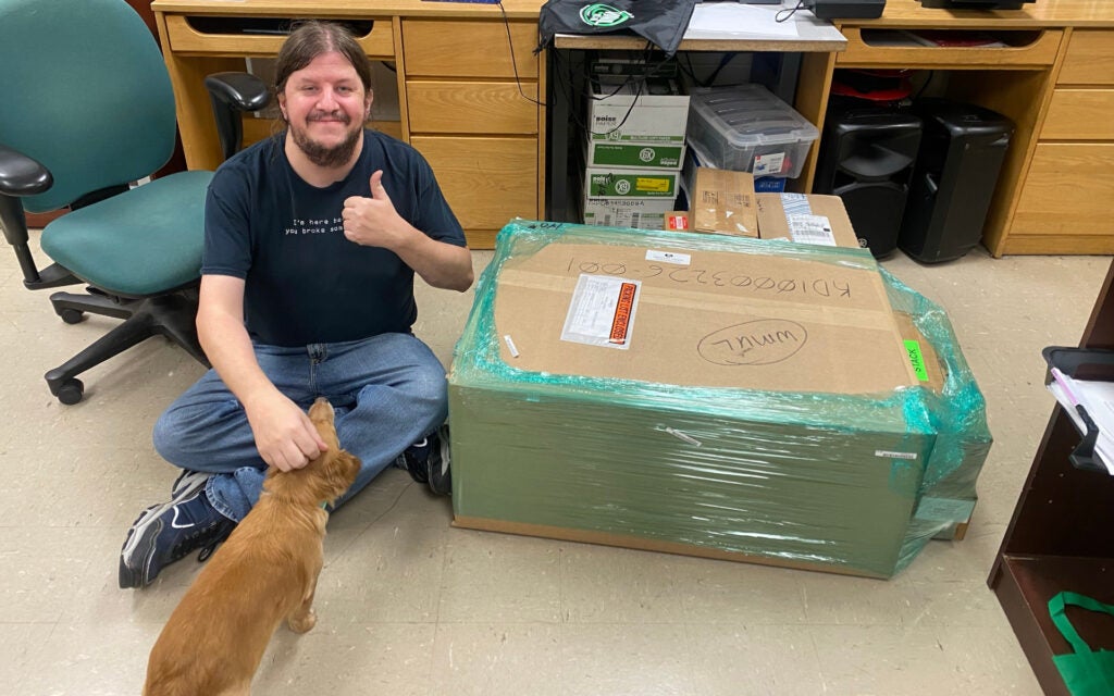
Most of the front panel of the new transmitter consists of an air filter for the fans. In the top middle are the buttons and display for local control. It can be controlled via the front panel or via software. The three cardboard boxes to the right contain the three power supply units. The new transmitter is about the size of a microwave oven. It does not require a separate exciter. This one unit can take audio in and output up to 5,000 watts of radio frequency energy.
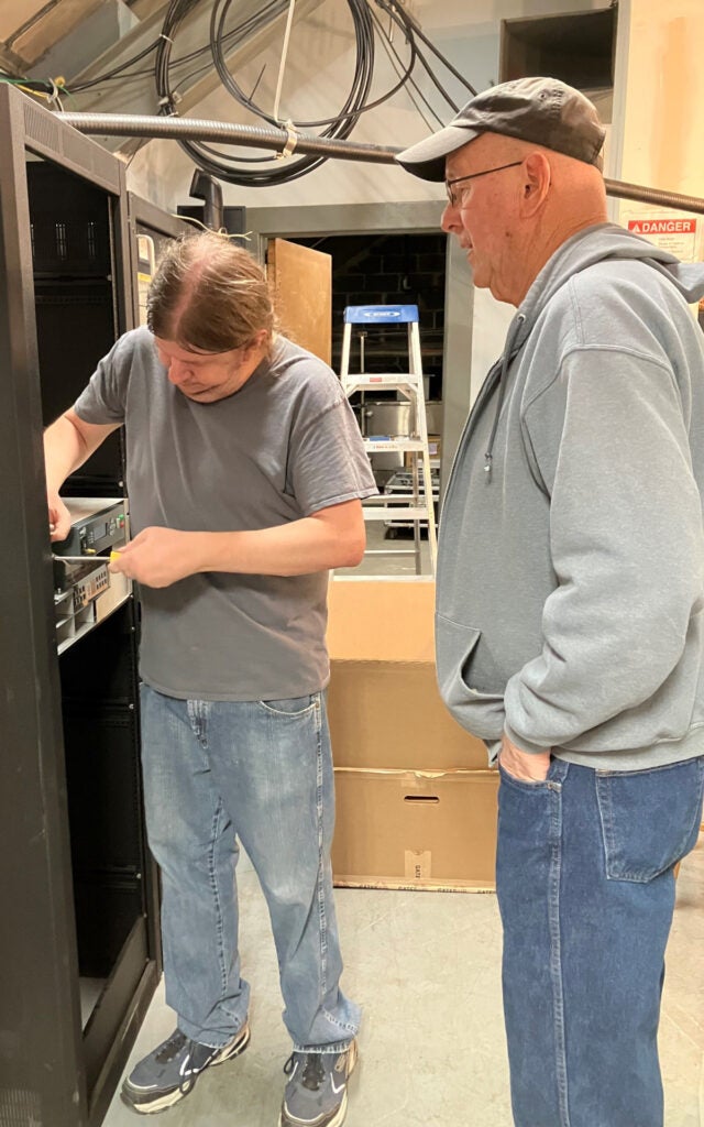
We signed our old transmitter off for the final time the morning of Wednesday, December 11th. It took most of the next two days to fully disconnect the old transmitter and hook up the new one. The old transmitter weighs over 800 pounds, so wrestling it out of the way was a group effort.
The green hose attached to the transmission line is a nitrogen gas line. The transmission line is pressurized to keep water out.
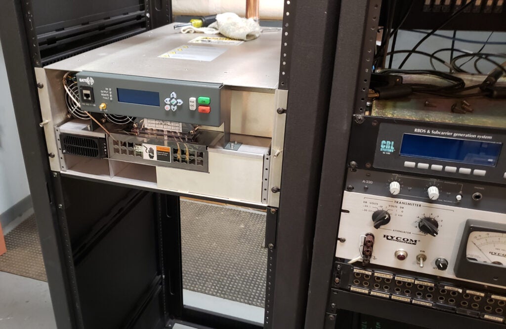
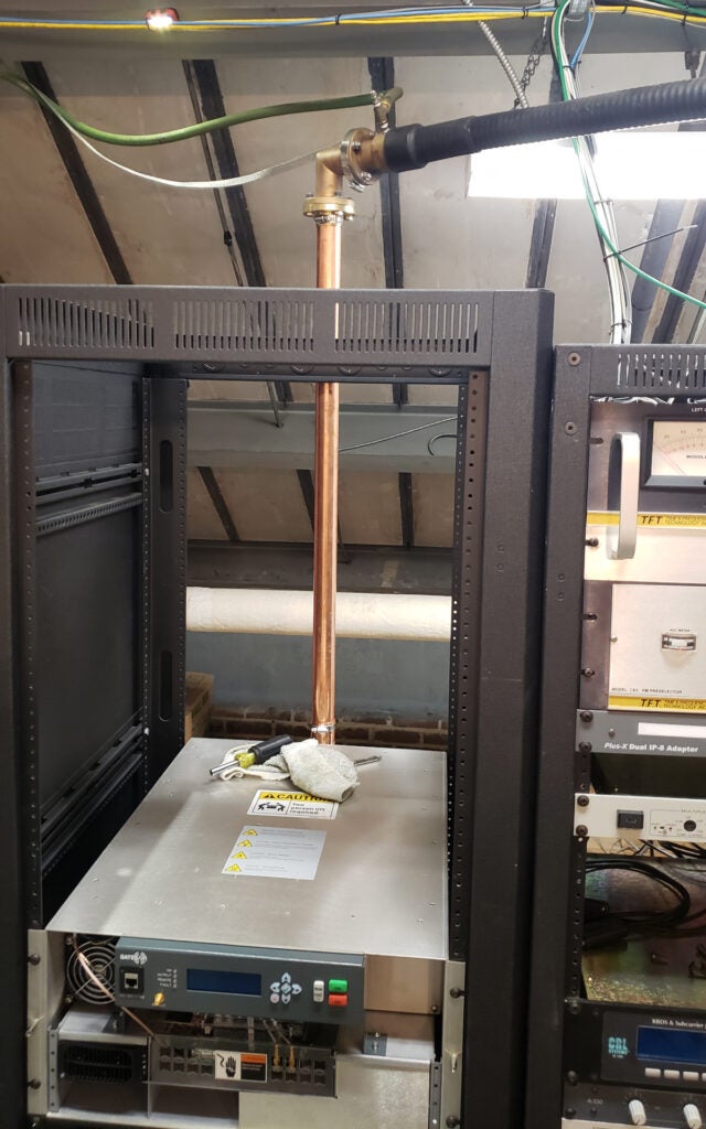
The new transmitter is partially installed at this point. The front panel with the air filters has been removed to permit access to the screw holes so that the new transmitter can be installed in the rack and so that the power supplies can be installed. The small black rectangular box in the lower left-hand side of the transmitter (just below the fans) is one of three power supplies. The two openings underneath the first power supply are for the other two power supplies. They are hot-swappable and the transmitter can operate at reduced power with only two power supplies.
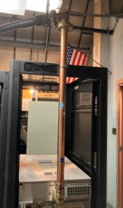
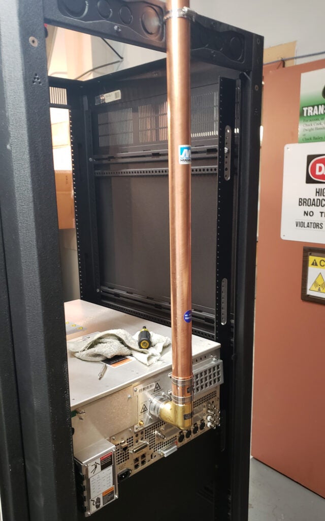
The new transmitter is connected to the existing transmission line via two new segments: an elbow on the back of the transmitter and a 3-foot long rigid vertical segment. The existing segments start with the elbow connector at the top. The black cable going to the left is the flexible line that goes up the tower. The white / beige cabinet in the background is the old transmitter.
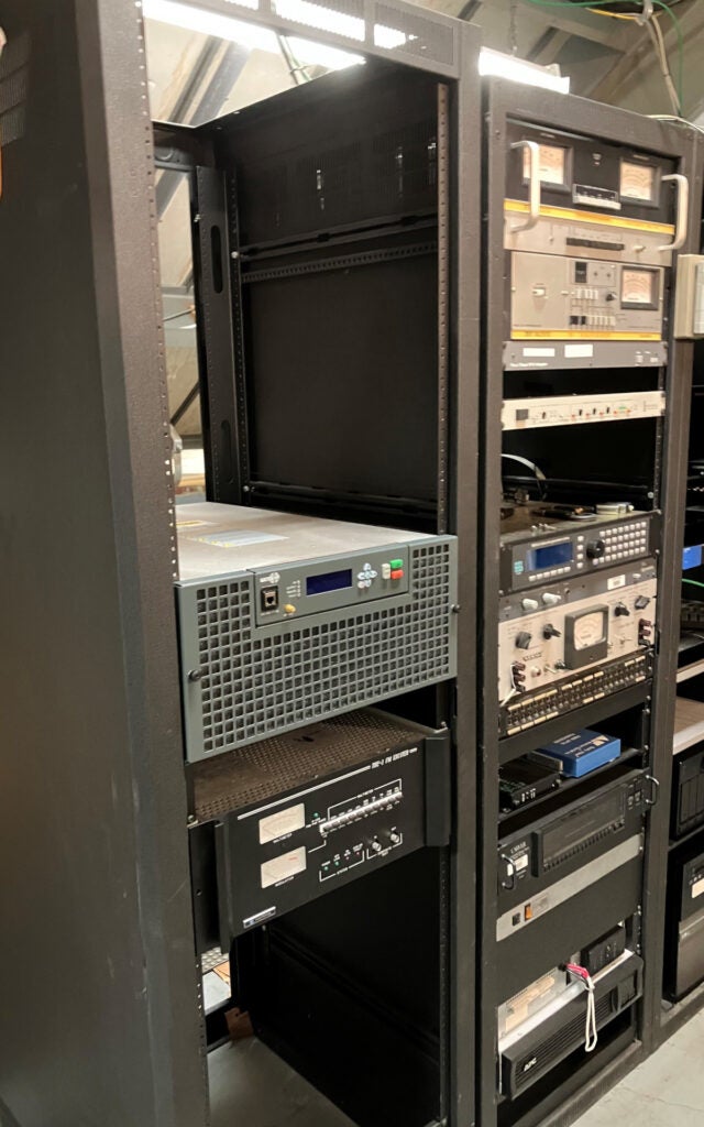
While the old transmitter was controlled using buttons, knobs, and switches, the new transmitter is fully controllable through software. Below the new transmitter in the rack is the old Harris THE-1 exciter (the black box with the two meters on the left-hand side). It can be configured to operate as a 55-watt transmitter, so it will be kept as an emergency backup.
The new transmitter was fired up during the afternoon of December 12, 2024 and has been blanketing the tri-state ever since.
Gallery
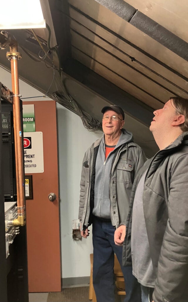
Here are a few more photos of the process.
